EMBEDDED SYSTEMS · BIOENGINEERING · 2024
Custom Benchtop Centrifuge
Phase-Aware Control, RPM Feedback, and Multimodal Notifications
Built a centrifuge from scratch by integrating a custom rotor and enclosure, Arduino-based motor control, optical speed sensing, an LCD interface, and phase-aware visual and auditory feedback.
- Role
- Embedded Systems & Bioengineering
- Team
- 3 people
- Controller
- Arduino
- Fabrication
- Laser Cut + 3D Printed
- Year
- 2024
Operating phases
Notification channels
Primary subsystem groupsControl · Sensing · Actuation
Digital-fabrication methods
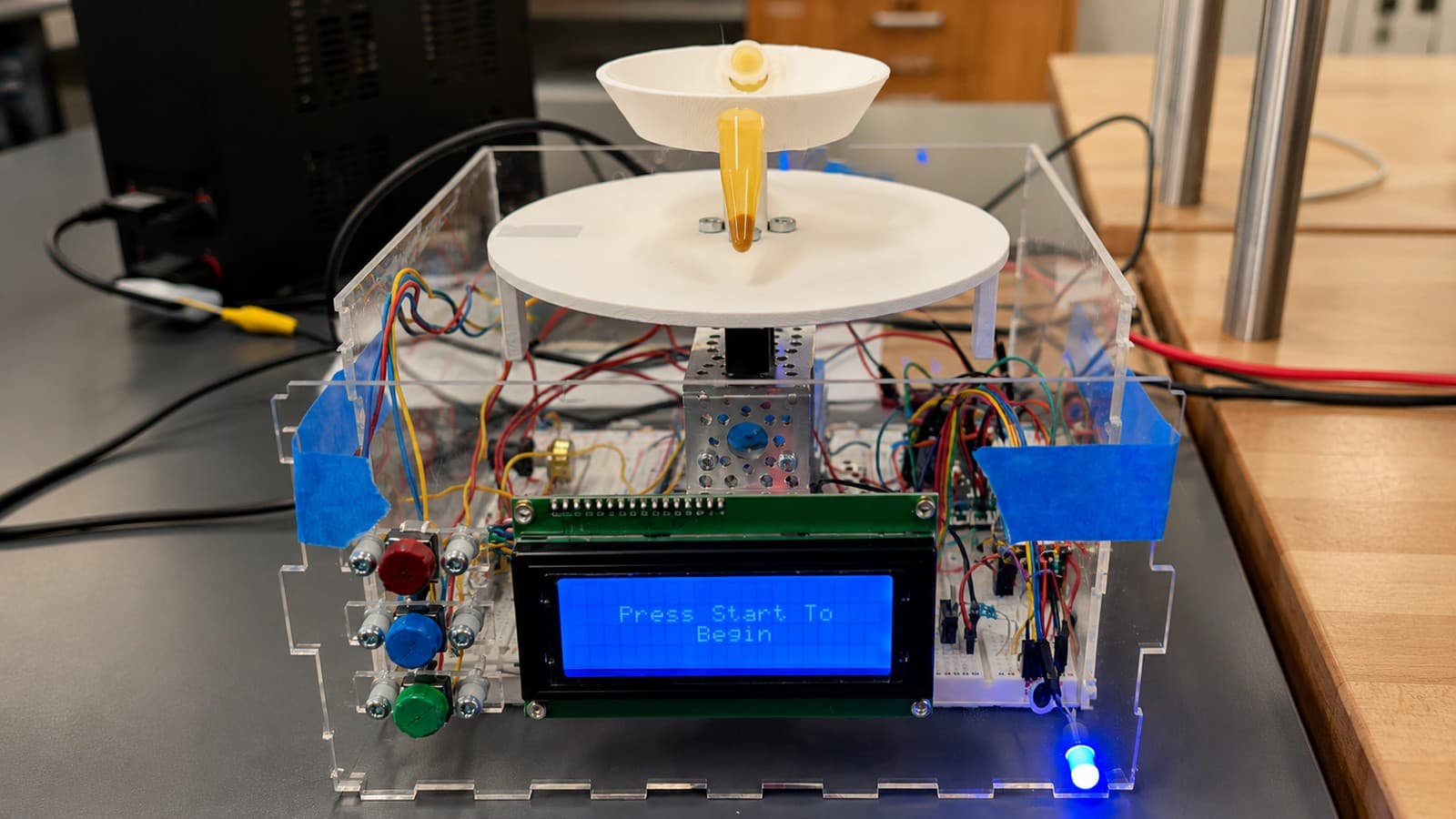
Integrated prototype
Overview
A centrifuge built from the inside out
We built a custom benchtop centrifuge from scratch, integrating a fabricated rotor and enclosure with Arduino-based motor control, optical RPM sensing, an LCD interface, and phase-aware visual and auditory feedback.
The device communicates its operating state through color and sound so an operator can distinguish setup, active centrifugation, ramp-down, and run completion without continuously watching the display.
The project combined mechanical fabrication, analog and digital electronics, embedded firmware, feedback sensing, and user-interface design in one integrated prototype.
Problem
A centrifuge should not require constant supervision
- Centrifuge runs may last long enough that an operator steps away.
- A display alone is not always noticeable from across a workspace.
- Motor sound does not clearly distinguish active spinning, ramp-down, and a fully completed run.
- Removing tubes before the rotor is stationary creates avoidable risk.
- The device therefore needed clear, redundant feedback about its operating state.
“How can a benchtop device clearly communicate what it is doing — even when the operator is not standing directly in front of it?”
The status system communicates run state; it is not a certified mechanical safety interlock.
Demo
One run, three clearly communicated states
- Operator loads balanced tubes
- Operator chooses time or speed
- Increase and decrease buttons modify the selected value
- Rotor remains stationary
Setup controls
Adjustable while the device is in Ready.
Current state: Ready. LCD reads “Press Start to Begin”.
Architecture
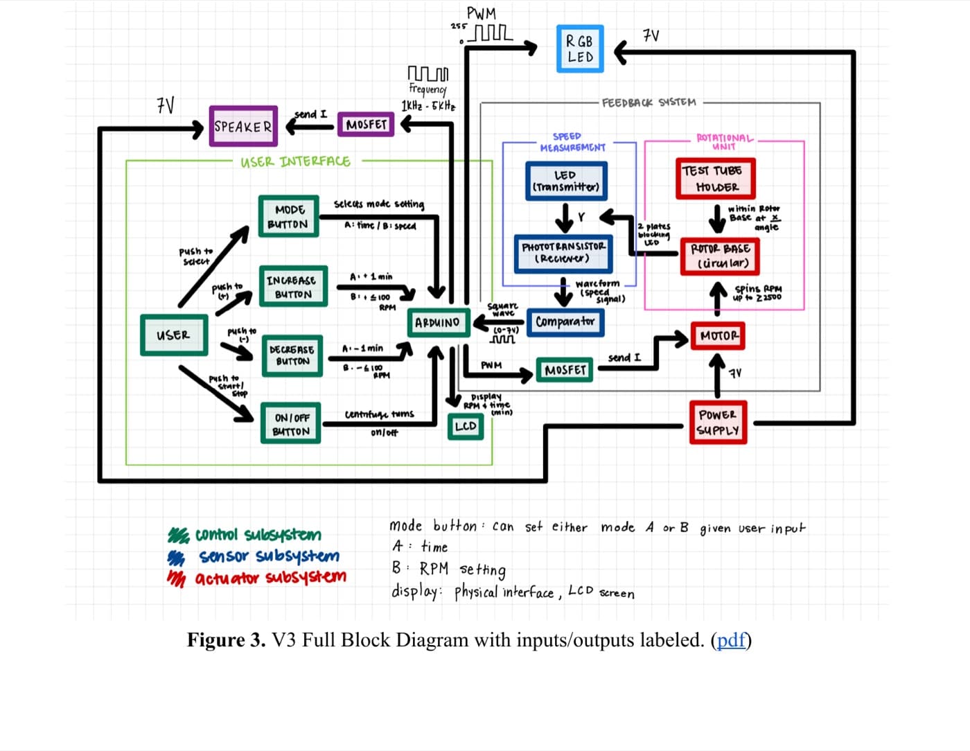
Full system architecture
User interface
- Mode selection
- Increase control
- Decrease control
- Start control
- LCD
- RGB status indicator
- Speaker
Controller
- Arduino
- Firmware state
- Time and speed setpoints
- PWM outputs
- Interrupt handling
- Sensor input processing
Sensing
- Optical transmitter
- Reflective rotor marker
- Phototransistor receiver
- Comparator
- Rotor pulse signal
- Estimated RPM
Actuation
- Motor driver MOSFET
- DC motor
- Rotor
- Tube holder
Supporting system: Power supply (7–9 V)
- OperatorArduinomotorrotor
- Rotoroptical sensorcomparatorArduino
- ArduinoLCD / light / speakeroperator
Built from mechanical, electrical, and software layers
Layer 1
Sample handling
- Tube holder
- Rotor bowl
- Rotor base
- Balanced sample placement
Layer 2
Mechanical drive
- Motor shaft
- Motor
- Mechanical support
- Rotor fasteners
Layer 3
Speed sensing
- Reflective marker
- Optical transmitter
- Phototransistor
- Comparator circuitry
Layer 4
Control electronics
- Arduino
- Motor MOSFET
- Speaker MOSFET
- Breadboards
- Power distribution
Layer 5
Operator interface
- LCD
- Buttons
- RGB LED
- Speaker
Layer 6
Enclosure
- Laser-cut transparent panels
- Front-panel openings
- Internal component mounting
- Wiring protection and organization
Fabrication
From CAD to a physical rotating system
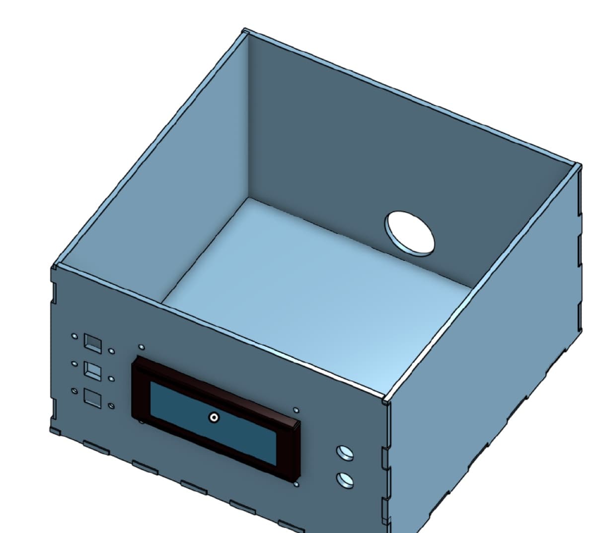
Laser-cut enclosure
- Custom panels were dimensioned for the physical device
- Front-panel cutouts accommodated the LCD, buttons, status light, and speaker
- Puzzle-style finger joints supported assembly
- Transparent material kept the prototype inspectable
- Components and wiring were contained within one enclosure
3D-printed rotor assembly
- A custom rotor base connected to the motor shaft
- A separate upper tube holder supported sample tubes
- Lower geometry incorporated elements needed for optical sensing
- Fasteners secured the rotating assembly
- Physical dimensions were checked after fabrication
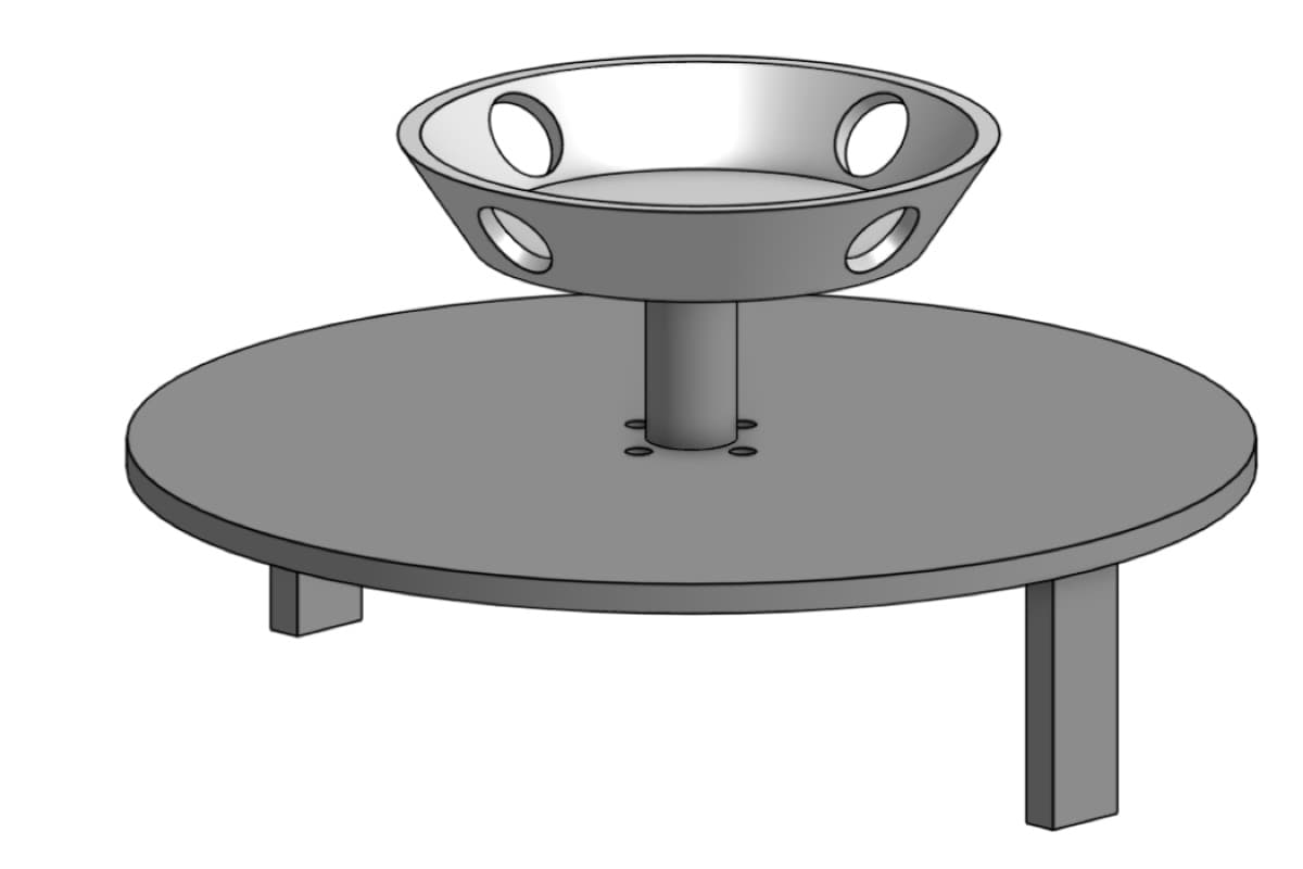
The larger two-level rotor improved organization and sensor separation, but its added mass reduced achievable rotational speed.
Designed, fabricated, measured, adjusted
| Location | Part | Designed | Measured |
|---|---|---|---|
| A–K | Enclosure base | 6–200 mm | Matched exactly |
| A–O | Enclosure right wall | 3–200 mm | Matched exactly |
| A–G | Rotor base (all views) | R1.8–R75 mm | Matched exactly |
- Enclosure base — A–K
- Designed: 6–200 mmMeasured: Matched exactly
- Enclosure right wall — A–O
- Designed: 3–200 mmMeasured: Matched exactly
- Rotor base (all views) — A–G
- Designed: R1.8–R75 mmMeasured: Matched exactly
Most fabricated dimensions matched the CAD targets closely.
None of these deviations prevented successful system integration — the enclosure required minor reinforcement with hot glue during assembly, which is normal prototype iteration rather than a failure.
Electronics
Turning a user-selected speed into motor motion
- PWM controlled the effective motor drive.
- The motor was switched through a MOSFET rather than driven directly from an Arduino pin.
- A flyback diode across the motor protected the driver circuit from inductive voltage spikes.
- Firmware mapped motor commands to measured rotor behavior.
- Sensor feedback improved the relationship between selected and achieved RPM.
This is best described as sensor-informed RPM control rather than a formal closed-loop (PID) controller.
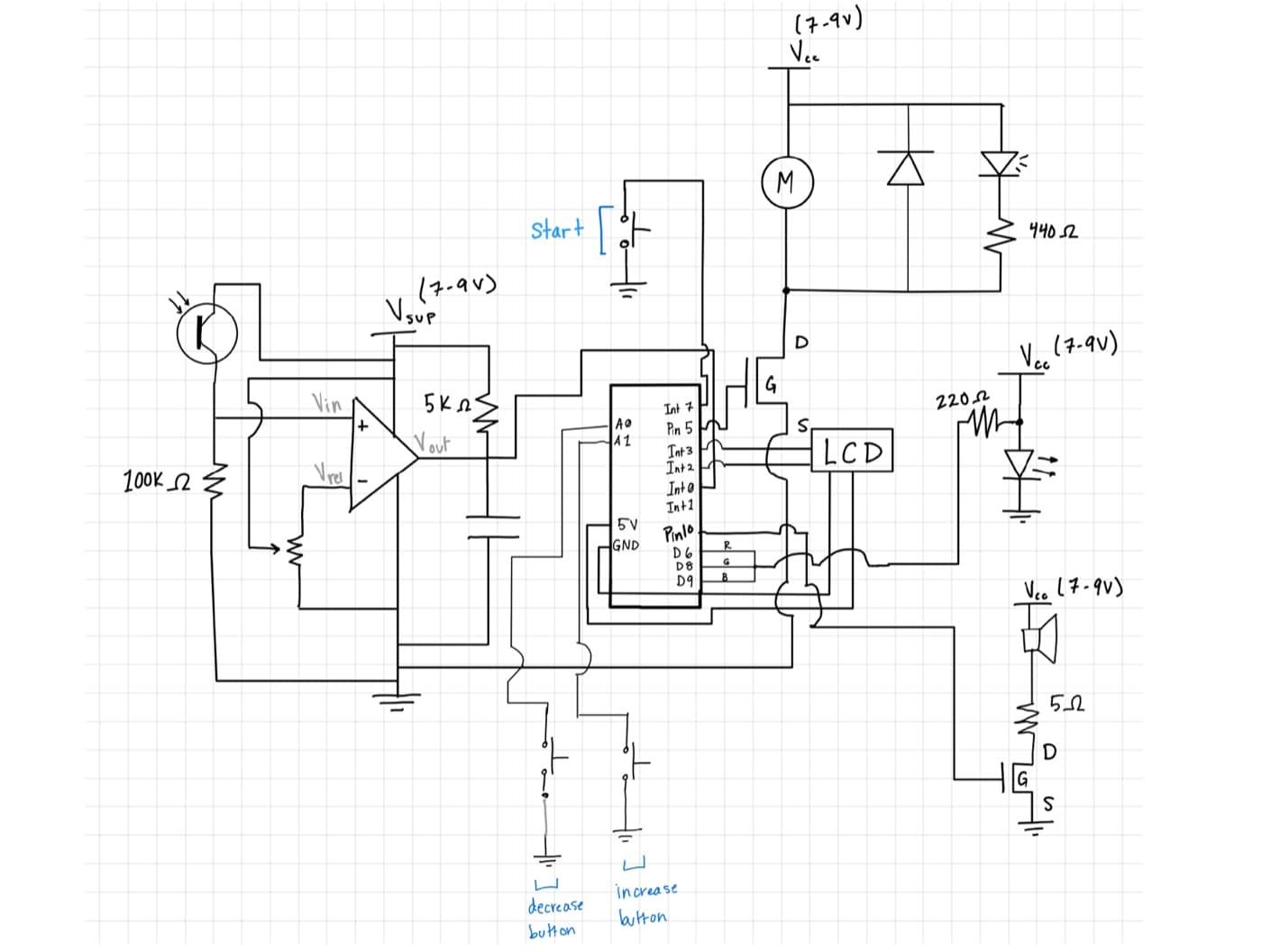
Measuring rotation without touching the rotor
- 1An optical source illuminates the rotor.
- 2A reflective marker passes the sensor once per revolution.
- 3The phototransistor detects the reflected-light change.
- 4A comparator converts the analog response into a cleaner digital pulse.
- 5The Arduino measures the pulse frequency.
- 6Pulse frequency is converted into rotor speed.
RPM = pulses per second × 60 / pulses per revolution
The rotor carried one reflective marker per revolution, so pulse frequency converts directly to RPM using this relationship.
Schematic trace — illustrative, not recorded scope data for this page.
Firmware
The centrifuge as a state machine
Flags and events
- Start button interrupt
- Start-cue flag
- Timer expiration
- Motor command
- Ramp-down completion
- RGB state
- LCD state
- Completion cue
- Physical buttons modify time or speed settings.
- The start control triggers the run sequence.
- Firmware coordinates motor output, timer state, LCD messages, lighting, and sound.
- Interrupt handlers remain short.
- Longer notification logic runs in the main loop.
The start event originated in an interrupt, but the audio sequence required delays. Instead of running blocking audio code inside the interrupt handler, the interrupt set a flag and the main loop played the cue safely afterward.
Avoid
Implemented
Notifications
One light, three understandable states
Blue — Ready
The device is powered and waiting for setup or a start command.
Yellow — Running
The programmed centrifugation cycle or ramp-down is active.
Green — Complete
The programmed cycle and ramp-down have finished.
Example run
Illustrative 11.5-minute run — segment widths are proportional to duration.
- A four-pin RGB LED was controlled through PWM-capable Arduino outputs.
- Firmware changed the output channels based on the current operating state.
- The system was first tested in circuit simulation.
- It was then tested on a breadboard.
- Finally, it was integrated into the complete centrifuge.
Color was paired with LCD text and audio cues so the interface did not rely on color alone.
Distinct sounds for start and completion
- 1Verify the speaker using a function generator.
- 2Test distinct frequencies.
- 3Connect the speaker to Arduino-generated square waves.
- 4Identify insufficient drive current.
- 5Add a MOSFET switching stage.
- 6Improve audibility during full-system integration.
- 7Create distinct start and completion sound patterns.
- 8Integrate both cues into the main firmware state machine.
if (startCuePending) {
    playStartCue();
    startCuePending = false;
}

if (runFinished) {
    playCompletionCue();
}
Testing
Integration challenges
Challenge 1
The start cue could not run inside the start-button interrupt
Decision
Set a startCueFlag inside the interrupt handler and play the audio cue from the main loop.
Lesson
Keeping interrupt handlers short and moving blocking logic to the main loop kept the firmware responsive and safe.
Challenge 2
The speaker was inaudible once wired into the full circuit
Decision
Add a MOSFET switching stage and reduce the current-limiting resistance to increase drive current.
Lesson
A subsystem that works in isolation can still fail once integrated — full-system testing caught a real audibility problem.
Challenge 3
The enclosure's interlocking panel design was hard to assemble reliably
Decision
Reinforce the puzzle-jointed panels with hot glue during final assembly.
Lesson
A transparent, inspectable enclosure was worth a small amount of manual reinforcement.
Challenge 4
Selected RPM did not always match measured RPM
Decision
Use phototransistor pulse feedback to inform and adjust the motor command rather than trusting the open-loop PWM value alone.
Lesson
Sensor feedback substantially improved the relationship between a selected and an achieved speed.
Functional testing
- The RGB LED was verified in circuit simulation, then on a breadboard, then in the fully integrated system.
- The speaker was verified against a function generator before being driven by Arduino-generated square waves.
- Laser-cut enclosure panels were measured after fabrication and compared against their CAD-designed dimensions.
- The rotor base was confirmed to spin true and stay securely fastened to the motor shaft.
Requirements verification
Safety-critical requirements around single-fault tolerance and hazardous emissions were assessed through a separate hazard-analysis process rather than the functional tests summarized here.
| ID | Requirement | Met? | Notes |
|---|---|---|---|
| 1.1 | Spin standard 1.5 mL microcentrifuge tubes | Yes | No changes needed. |
| 1.2 | Spin two identical containers simultaneously while maintaining basic safety | Yes | No changes needed. |
| 2.1.1 | Support rotational speeds of at least 2,500 RPM | No | Would need a motor with higher voltage capacity, since the larger rotor base needed more power. |
| 2.1.2 | Allow the operator to set speed in increments of ~100 RPM or less | Yes | No changes needed. |
| 2.1.3 | Allow the operator to set speed accurately to within ~5% error | Yes | No changes needed. |
| 2.1.4 / 2.1.5 | Ramp up or down within ~30 seconds without exceeding the speed setting | Yes | No changes needed. |
| 2.1.6 | Maintain speed within ~5% of setpoint throughout a run | Yes | No changes needed. |
| 2.2.1–2.2.3 | Allow programmable run duration (up to ~10 min, ~30 sec increments, ~5% accuracy) | Yes | No changes needed. |
| 3.1 / 3.2 | Start within ~1 sec and stop/ramp-down within ~0.5 sec of a command | Yes | Initiation was not perfectly consistent — a more reliable button-input system would help. |
| 4.1.1 / 4.2.1 | Notify the operator visually and audibly at run start and at safe-removal time | Yes | No changes needed. |
| 5.1 | Separate anticoagulated blood into three distinct layers within ~5 minutes | No | The motor was not powerful enough to reach the rotational speed this separation required. |
| 5.2 | Pellet turmeric particles from a test suspension within ~2 minutes | No | This verification test was not completed. |
| 7.2.1 / 7.2.2 | Resist tipping on a flat surface or a ~5° incline | Yes | No changes needed. |
| 7.3.1 / 7.3.2 | Contain spillage without wetting components that affect safety | Unsure | Testing was not performed, out of caution around wetting live electronics. |
- 1.1 Yes
- Spin standard 1.5 mL microcentrifuge tubes
- No changes needed.
- 1.2 Yes
- Spin two identical containers simultaneously while maintaining basic safety
- No changes needed.
- 2.1.1 No
- Support rotational speeds of at least 2,500 RPM
- Would need a motor with higher voltage capacity, since the larger rotor base needed more power.
- 2.1.2 Yes
- Allow the operator to set speed in increments of ~100 RPM or less
- No changes needed.
- 2.1.3 Yes
- Allow the operator to set speed accurately to within ~5% error
- No changes needed.
- 2.1.4 / 2.1.5 Yes
- Ramp up or down within ~30 seconds without exceeding the speed setting
- No changes needed.
- 2.1.6 Yes
- Maintain speed within ~5% of setpoint throughout a run
- No changes needed.
- 2.2.1–2.2.3 Yes
- Allow programmable run duration (up to ~10 min, ~30 sec increments, ~5% accuracy)
- No changes needed.
- 3.1 / 3.2 Yes
- Start within ~1 sec and stop/ramp-down within ~0.5 sec of a command
- Initiation was not perfectly consistent — a more reliable button-input system would help.
- 4.1.1 / 4.2.1 Yes
- Notify the operator visually and audibly at run start and at safe-removal time
- No changes needed.
- 5.1 No
- Separate anticoagulated blood into three distinct layers within ~5 minutes
- The motor was not powerful enough to reach the rotational speed this separation required.
- 5.2 No
- Pellet turmeric particles from a test suspension within ~2 minutes
- This verification test was not completed.
- 7.2.1 / 7.2.2 Yes
- Resist tipping on a flat surface or a ~5° incline
- No changes needed.
- 7.3.1 / 7.3.2 Unsure
- Contain spillage without wetting components that affect safety
- Testing was not performed, out of caution around wetting live electronics.
This prototype demonstrated an integrated electromechanical system and phase-aware interface — it did not demonstrate laboratory-grade separation performance, clinical use, regulatory compliance, or a production-ready safety system.
My role
Team contributions
Mechanical design and fabrication
- Designed and laser-cut the enclosure panels in CAD
- Designed and 3D-printed the two-level rotor and tube holder
- Measured fabricated parts against CAD targets and made manual adjustments where needed
Electronics and sensing
- Built the phototransistor and comparator optical-sensing circuit
- Built the motor and speaker MOSFET driver stages
- Wired and tested the full circuit on breadboards before integration
Embedded firmware
- Implemented the run state machine in C/C++ on Arduino
- Implemented interrupt-safe handling for the start event
- Mapped PWM motor commands to sensor-measured rotor speed
Notification systems
- Implemented phase-aware RGB status lighting
- Composed and implemented distinct start and completion audio cues
- Integrated both notification channels into the main firmware loop
Testing and verification
- Ran subsystem tests for the RGB LED, speaker, and sensing circuit
- Ran full-system functional tests and documented requirement-by-requirement results
- Documented fabrication measurements against CAD targets
Reflection
Lessons and future improvements
What we learned
- A more powerful motor is the single highest-leverage change for meeting the higher-speed requirements.
- A more reliable button-input system would make run start and stop timing more consistent.
- The turmeric-pelleting verification test should be completed to properly assess particle-separation performance.
- A formal safety review would be needed before handling any biological sample, let alone anticoagulated blood.
What we’d do next
- Upgrade to a higher-power motor and re-validate achievable RPM
- Redesign the button input circuitry for more consistent start/stop timing
- Complete the turmeric-pelleting verification test
- Add a certified mechanical lid interlock
- Explore automatic imbalance detection
- Pursue a formal hazard analysis and risk-management review before any biological sample use
Tech & topics
- Arduino
- C/C++
- Embedded Systems
- Motor Control
- PWM
- Optical Sensing
- CAD
- Laser Cutting
- 3D Printing
- Bioengineering